Floors Shear And Moment Diagrams

Shear And Moment Diagram Of First Floor Cd Download Scientific Diagram
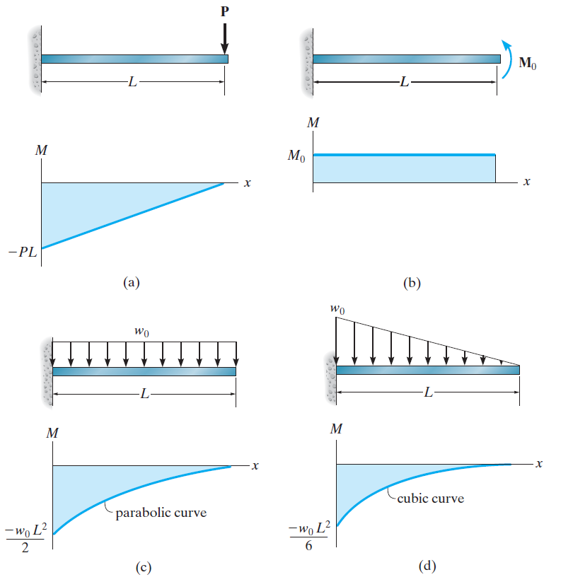
Moment Diagrams Constructed By The Method Of Superposition

Shear And Moment Diagrams Civil Engineering Construction Engineering Structural Analysis
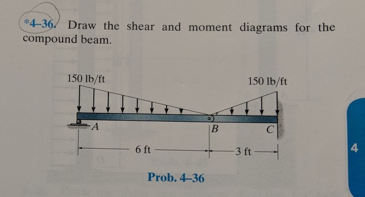
Solved Oke 4 36 Draw The Shear And Moment Diagrams For Th Chegg Com

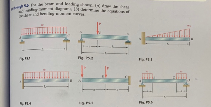
Solved 1 Draw The Complete Shear Force And Bending Momen Chegg Com

Hydrodynamic Load And Resulting Shear Force And Bending Moment Diagrams Download Scientific Diagram

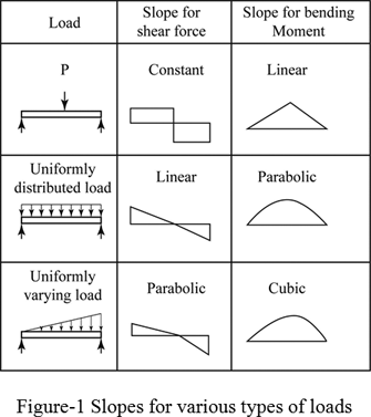
4 4 area method for drawing shear moment diagrams useful relationships between the loading shear force and bending moment can be derived from the equilibrium equations.
Floors shear and moment diagrams.

Log Debris Impact And Resulting Shear Force And Bending Moment Diagrams Download Scientific Diagram

Shear Force And Bending Moment Diagrams This Site Provides A Great List Of Variables For The Mechanical Equations It Shows The Shear Force Ingenieria Mecanica

Statics Lecture 26 Internal Forces Shear Force And Bending Moment Functions And Diagrams Shear Force Bending Moment Force

Solved 3 The Load Shear And Moment Diagrams Are Provide Chegg Com

Storey Shear And Moment Diagrams Of The Solid Wall And Opened Masonry Wall Download Scientific Diagram

Shear Force And Bending Moment Diagrams This Website Is Useful Because It Explains Poin Civil Engineering Design Bending Moment Civil Engineering Construction
Definition Of Shear And Moment Diagrams Chegg Com
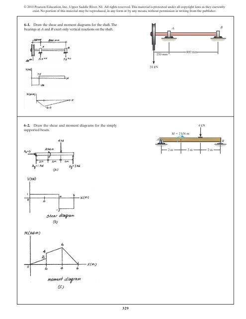
329 6 1 Draw The Shear And Moment Diagrams For Aerostudents

For The Beam And Loading Shown Draw Shear Bending Moment Diagrams Chegg In 2020 Bending Moment Beams In This Moment

Draw Shear And Moment Diagrams For Cantilever Beam In 2020 In This Moment Beams Diagram

Mechanics Ebook Shear Moment Diagrams Civil Engineering Design Civil Engineering Construction Structural Engineering

Pin On Structural Engineering

Draw The Shear And Moment Diagrams For The Beam Study Com

Shear And Moment Diagrams S B A Invent Nursing Student Tips Structural Analysis In This Moment
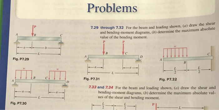
Solved Problems 7 29 Through 7 32 For The Beam And Loadin Chegg Com

Draw Shear And Moment Diagrams For The Overhang Beam In 2020 In This Moment Draw Diagram Text Drawing

Simply Supported Udl Beam Formulas Bending Moment Equations Engineering Design Civil Engineering Design Civil Engineering
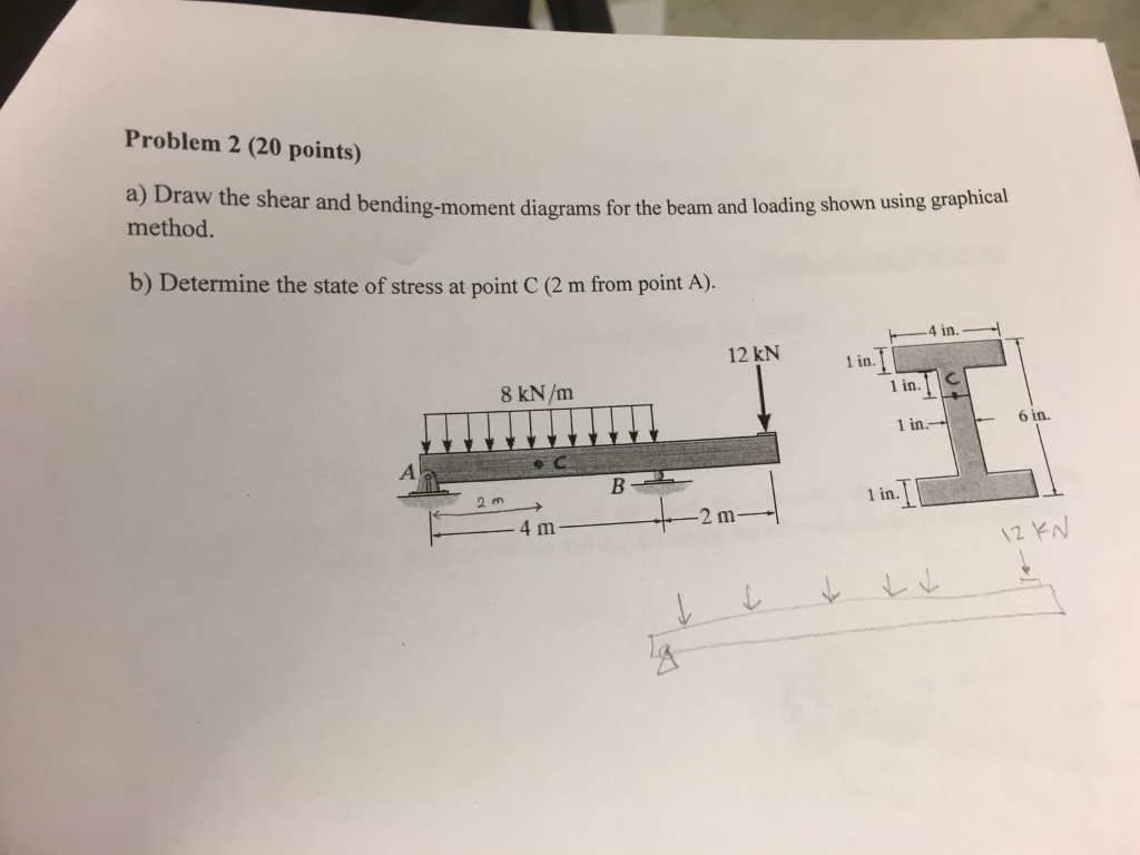
Solved For The Beam And Loading Shown A Draw Shear And Chegg Com
3

Pin On Structural Engineering

Pin On Vigas

Shear Force And Bending Moment Diagrams This Website Is Useful Because It Explains Poin Civil Engineering Design Bending Moment Civil Engineering Construction
Solved A Draw The Shear And Bending Moment Diagrams For Chegg Com
Solved Draw The Shear And Moment Diagrams For The Beam Ab Chegg Com
Source : pinterest.com
